This document provides a more
detailed view of the Product Catalog System through a breakdown of each
subsystem into classes and how the classes interact with each other. This
document is setup to provide details about the Master Data Definition that will
be used for the system and then follows with a description about the subsystems
and how they interact with each other. The subsystems UI View, UI/System
Management, Entity Management, XML/Persistence and Export are all discussed in
the later sections after the overall system design and are depicted using UML
class diagrams to convey their details and structure.
The overall purpose
of this document is to provide the stakeholders with a more fine-grained
visualization of what the system will look like when it is implemented. Within
the design of the system several Gang of Four design patterns such as the
strategy pattern, decorator pattern, builder pattern and singleton patterns are
used to help provide some basis and core stabilization to the system design.
The use of these patterns helped provide a system that contains low-coupling
and flexible to allow for future modification without much trouble.
Product catalogs
are defined as a hierarchical structure of entities. The following is a
breakdown of each of the entities and what can be contained within them.
Product
Catalog: Contains products, attributes, and business rules.
Product:
Contains features, attributes, connection numbers, and products.
Feature:
Contains attributes and features.
Attribute:
Contains no other entities. An attribute does contain any number of
conditions and a default result.
These
two definition elements are described below.
Connection
Number: Contains no other entities.
Business
Rules: Contains references to products, features, attributes, and/or
connection numbers.
These are
parameters that are not common to all entities. All parameters are listed with
their possible values
Feature:
·
Pricing:
{Optional, Required, Recommended}
Attribute:
·
Profitability:
{N/A, Yes, No}
·
Commissions:
{N/A, Yes, No}
·
Waivability:
{N/A, Yes, No}
·
EMR: {N/A,
Yes, No}
·
Pricing: {N/A,
MRC, NRC, Usage}
·
MMF: {N/A,
0-100%}
These elements are
not entities in the definition. Their purpose is to help describe the hierarchy
or assist in the description of an existing entity.
Root:
This is the parent element in our hierarchy. It contains a reference to every
product catalog in the system.
Condition:
This element describes one condition that may be applied to an attribute. It
contains any number of expressions and one result. If all the expressions pass
the values described in the result should be used.
Expression:
This element describes a Boolean expression. The expression contains a
reference to any attribute in the product catalog, an equivalency operator, and
a value.
Result:
This describes what values the attribute should use if the condition is
met.
Products and
product catalogs will be defined and stored in SVN as three different XML file
types:
Product File: Contains all product
related information such as description and name. It will also contain every attribute,
feature, connection numbers, and references to other products.
Product Catalog File: Contains what
version the product catalog is, contains attributes and business rules and references
to the products within it. This also contains product catalog specific
information such as a name and description. The business rules that are
contained within this file will reference multiple products or entities contained
within multiple products.
Root File: There will be one root file
that contains a reference ID to every product catalog in the system.
This Entity
Relationship Diagram shows which entities can be contained by other entities,
and how entities are related. Multiplicities are shown for each compositional
relationship. This is not a class diagram, which would show member data and functions.
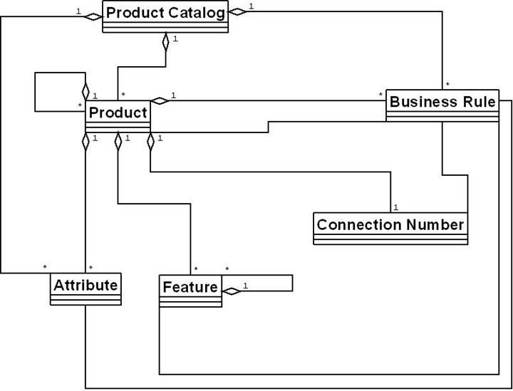
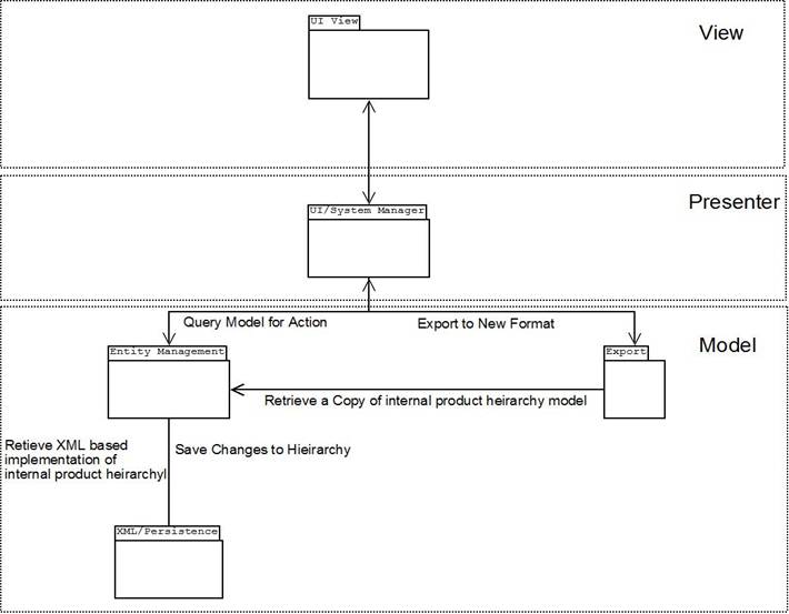
From a subsystem standpoint, this diagram
shows a high level view of the system.
The UI
View subsystem will be responsible for providing and handling user input
and then sending them to the UI/System
Manager subsystem. This interaction between the UI View and UI/System
Manager will be implemented using Google Web Toolkit (GWT), which provides
the system with a GUI that can be easily removed, while at the same time also
providing a means for communication between the client and the server using GWT
Remote Procedural Calls (GWT RPC).
The UI/System
Manager, once it is provided with a request from the UI View, will determine how to handle the request and which other
subsystems it will be needed to complete the transaction with the client.
The Entity
Management subsystem will be
responsible for maintaining a collection of the entities i.e. Products,
Features and etc. It will also provide the interaction with the XML/Persistence Subsystem that handles
all transactions with the Subversion (SVN) repository.
Finally the Export subsystem will be responsible for allowing the user to
export to a format that is foreign to the Product Catalog System and will
provide the user with ways to define the format that they wish to export to.
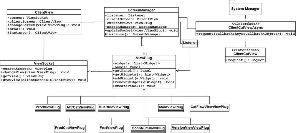
The UI
View as mentioned previously will handle all user interaction and will
maintain the connection to the server using GWT RPC. In this subsystem there
are a few key classes and patterns at work.
The first is the idea of a ClientView, which is a digital
representation to the system of what the user will be seeing and interacting
with. The ClientView will contain a ViewSocket that is able to have
different views plugged into it based upon user interaction. ViewSocket is used to contain the actual
screen that the user will see and will draw it to the screen upon being
prompted by the ClientView. The ScreenManager manages the ClientView and all the entities that
exist on the client side, as it will send the RPC request to the server and
then will format the output it receives into what is called a ViewPlug.
The ViewPlug
is the type of screen that the user will see, by utilizing a decorator pattern.
Each plug will fit into the ViewSocket
and can be changed as mandated by the ScreenManager,
when the next view is to be shown to the user. The actual plugs themselves will
be created on the server side and then passed back through the RPC callback
value and then un-marshaled into the view.
Finally the ClientCatViewAsync and ClientCatView
are the GWT RPC interfaces that will be created in order for the client to
actually communicate with the server.
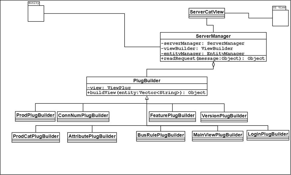
This subsystem will be responsible for
handling all client side requests and getting the appropriate response sent
back. There are two major players in this portion of the system, the ServerManager and the ViewCreator.
The ServerManager
will be used to determine where to get the information needed to respond to the
client. ServerManager is a singleton
because there should be only one ServerManager
receiving requests and then talking to the rest of the system. It could possibly
create a state issue within the system; therefore the singleton pattern is used
to prevent this from occurring. The ServerManager
will determine if it needs to contact the Entity
Management Subsystem or the Export
Subsystem for outside contact, however it can also talk with the ViewCreator.
The ViewCreator
will be responsible for managing the building of the view plugs. This is done
through a builder pattern, where a view is created when the ViewCreator determines which view will
need to be created for the next user screen based upon what it is given for
information from the ServerManager.
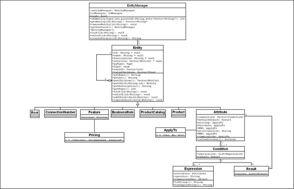
This subsystem will maintain the system
model of the product catalog hierarchy and will provide the UI/System Manager with the ability to
manipulate the system model and the underlying file system that is setup in SVN. This is set up using a composite
type entity that can be many different types of entities such as a Product or Feature. The parent class, Entity,
is abstract, and cannot itself be instantiated as a type, however, its
children, which share all the elements found within Entity, are concrete.
The relations between different entity
objects, illustrated earlier in the visual representation will be enforced via
the implementation of the validTypes
element of each entity, which will consist of a list of other entity types that
are able to be attached to each class as a child. The addEntity method in EntityManager
and the addChild method in Entity will facilitate the creation of
a Product Catalog’s structural hierarchy, and re-build said hierarchy each time
it is re-read from XML.
Through polymorphism each entity will be
able to have access to a list of entities that it contains and that will be
shown when a view for this entity is created. The EntityManager is responsible for maintaining a consistent and
correct representation of the product hierarchy and for communicating with the ServerManager and the XML/Persistence subsystem.
The Condition,
Expression, and Result classes exist to capture a conditional restraint on an Attribute object. Each Attribute can contain multiple Condition objects, which each be made
up of one or more Expression and a
single Result. The Expression will contain a reference to
the outside attribute whose value is being used as a constraint, along with an
operator (<, >, =, etc…) and a value for comparison, to determine if the
condition is met. Each Result will
contain a list of valid values given the condition is satisfied. The Attribute itself will also contain a
single Result, which will be used to
represent its default set of valid values.
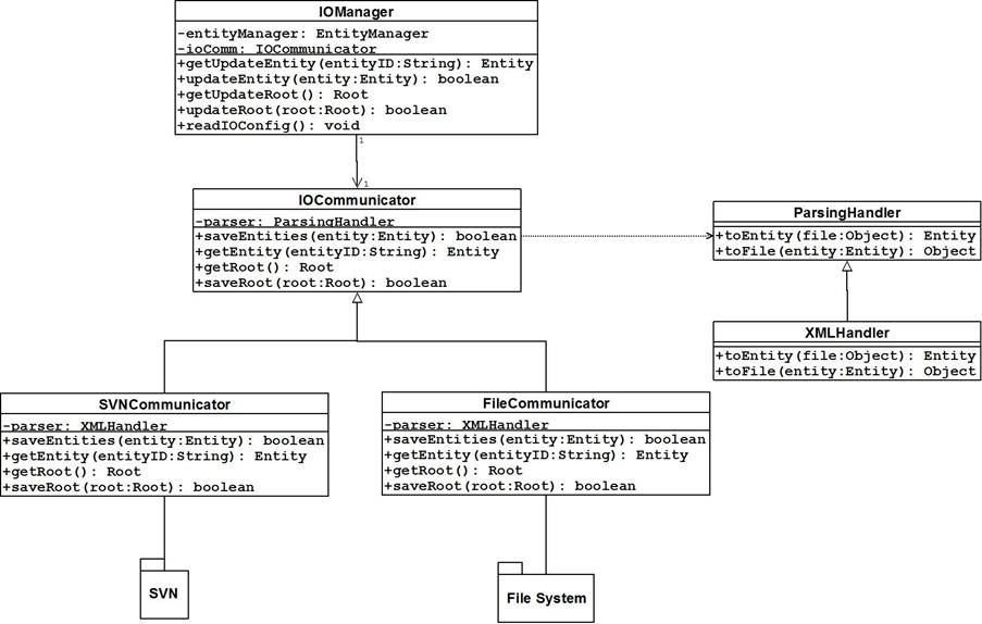
This subsystem will have full responsibility
for communicating with the SVN
repository, by updating and committing changes that were done in the system
model. The IOManager will be
responsible for communicating with the EntityManager,
by providing access to the IOCommunicator.
IOCommunicator is a class that is
extended by FileCommunicator to communicate
with the file system, and can be
further extended by SVNCommunicator
to communicate with the SVN server,
should this feature be implemented (diagram retains this class to illustrate
its intended location should the extension be made). The Communicator objects will utilize a corresponding ParsingHandler object that will be used
to convert to and from entity objects. Currently the concrete parser available
will be the XMLParser. This
subsystem follows an abstract factory pattern that provides the system with the
ability to be adapted to a different form of persistence, such as an Oracle Database
at a later time. To change the form of persistence a Communicator class and a Handler class will have to be created to
provide specifics as to how an entity should be represented in the persistence.
(It should be noted that a new handler class is not needed if the format in which
the files are saved is unaltered. For example, to support SVN, only a new Communicator
class need be implemented, since both the current file system implementation
and the SVN server would store files
formatted to satisfy our XML schema.)
XML parsing will be done by the native Java
XML parser JAXP. The reason for this is that JAXP contains both DOM and SAX
implementations that can be utilized as needed. This will provide flexibility
from the standpoint that if one particular solution does not fit during
development, the other method can be used instead. Secondly, there would be no
need for a reliance on an external library, thus providing no licensing issues
and compatibility issues with Java, as it has been supported since Java 1.4 and
this system shall be implemented using Java 1.5.
Some of the rejected libraries were dom4j,
XMLPULL, and JDOM. They were rejected due to the fact that JAXP seemed to be a
better alternative by providing a couple different approaches to XML Parsing.
These libraries would also be external to Java and could pose reliance and
licensing issues.
For Java interactions with SVN, we have
chosen the SVNKit libraries. SVNKit was chosen because it has an easy to use interface,
where every function is mirrored by an SVN command-line command. It was also
chosen because SVNKit is currently in use at PAETEC, which means there are no
licensing issues.
A rejected alternative was the JavaHL
library. This library was considered in case there had been licensing issues
with SVNKit, and rejected when SVNKit was cleared for use. JavaHL is an
underlying component in SVNKit, and the interface is not as intuitive and easy
to link to SVN command-line commands.
This diagram illustrates the creation of a completely new
product from start to finish. It goes through the creation of a new Product
object within the Entity Management subsystem based on the incoming user
request. Following this is the creation of a new file to persist the gathered
data, its translation from an object representation to XML (via the XMLParser),
and finally the saving of the file in the file system. Finally, the diagram
shows the path travelled to display the newly-created Product to the user,
which illustrates communication back from the server to the client side, initiating a view change to display the input
information as a new Product object to the user.
This diagram demonstrates what occurs when a user views all
the catalogs that exist within the system. The client upon loading this view
sends a request to the server for all the catalog names and IDs that exist
within the model. The server then structures the request into a format that the
EntityManager will understand and passes control to the Entity Management
subsystem. Upon being told to get the product catalog names and IDs, the
EntityManager queries the root entity to give it this information, so that it
can be packaged and returned to the UI. After the information is retrieved, the
EntityManager formats it in such a way that the ServerManager can understand.
At this point, the information is then given to the appropriate view builder to
format the information in a way that the corresponding UI Plug will be able to
understand. The information is then returned to the UI by way of a callback
from the request sent earlier. Once on the UI side, the data is placed in the
correct view and then that view is drawn to the screen.